Tl;dr: how tf does wiring 15khz from jamma work with the buffer board? I only have the buffer board and not the full kit, so im planning to make my own harnesses. Pics appreciated. ")
So I have two cabs atm that I would very much like to have the option to link- a blast and astro city. Now hang on, before you go all "You need a 2nd Blast I/O" on me, I know that. Hear me out.
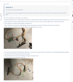
For starters I 300% plan to get mikes VS board whenever that is finished up, but until then, I just wanna explore my options. I don't have the Entire Blast vs kit, but my blast DID come with the video buffer board. This goes into my second point: "Why not just make a VS cable out of some jamma fingerboards??" If you read up on this like I've tried to do, you'll find one handful of people going "I made this and it works great for me!" then another handful of people saying "OK but your video is either going to be dim or have poor sync since you're splitting the signal in half. Also you should do something to put the 5v on the 2nd cab under load." The buffer board that I have should solve that split signal issue, though I have some questions about it since I feel like I'm getting some conflicting info from the manual and AO Wiki. Obviously this thing is just meant for connecting one blast to another, but the manual does say that it supports both VGA and Jamma; i.e. a 15khz signal. Myhope plan is to just build some cables myself to compensate for the missing harness out of (maybe?) an original JST RA on the blasts I/Os C7, then a DB15 -> astro RGB in from the video buffer board. I'll be putting all the pics behind spoilers so the thread is a little less cluttered, but for reference, here's the buffer board so you have an idea of what I'm looking at/thinking about:

Here's the first part of my conflicting info:

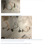
This isnt official- it's just a cute little diagram someone made and put up on the AO wiki that describes how to connect to the buffer board form a Jamma PCB. I can't really tell what the "001" loom is, since the only thing I know for sure that connects to the Blast I/O board is the short DC 12V harness that powers the buffer board. Otherwise, it COULD be the RGB-in from jamma, but it's hard to tell becuase...

Here's a sc from the VS kit manual. The 6pin header on the buffer board shows rgb signals going (what I assume is) into the buffer board from the blast I/O at c7, then OUT via DB15, then connected to the other blasts I/O by another 6 pin harness...making the cn7 port both an RGB in, AND out? The rest of the inputs from cn7 travel through that JST RA connecter to a panel the vs kit came with that I dont have- no biggie, the plan is just to make my own harness for controls anyways since there's no worries about sync or anything like there is with the video. In fact, if I just look at the pinouts for cn7 in the blast manual I should be able to figure out if cn7 is an RGB-in or out, and then...
(Edit: Just now seeing I missed the "NO USE" on the rightmost side terminal board for 2P. I'm guessing this confirms that the RGB lines on cn7 are definitely an OUT? Since the DB15 on the buffer board goes up into the d-sub input on the monitor from there lmk if I've got that right. Anyways, about the remaining pins...)

...oh. The Blast manual doesn't HAVE cn7s pinouts...and neither does the VS kits manual...awesome
I have a feeling something simple is just soaring over my head right now, so if you wanna point me in the right direction, it would definitely be appreciated lol. Also, if you happen to have pics of a VS kit you have using rgb from jamma, that would definitely help as well. Would also like suggestions for good methods of putting the astros 5v under load without a game board.
The "big jamma fingerboard harness" Could work if im only using it for easily routing the 2P controls, so if the JST RA pinouts don't poof into existence so I can go about it that way, I'm thinking about maybe like...soldering a jamma edge to one end of a fingeboard for the 2P side, plugging in a spare cheap dotorikun there, then cutting the traces or hijacking the wires for controls/video/sound/etc so the only thing the dotori is there for is to have something occupying the 5v line. I'm no electrician, so that's just my spitball "using what ive got" idea 
So I have two cabs atm that I would very much like to have the option to link- a blast and astro city. Now hang on, before you go all "You need a 2nd Blast I/O" on me, I know that. Hear me out.
For starters I 300% plan to get mikes VS board whenever that is finished up, but until then, I just wanna explore my options. I don't have the Entire Blast vs kit, but my blast DID come with the video buffer board. This goes into my second point: "Why not just make a VS cable out of some jamma fingerboards??" If you read up on this like I've tried to do, you'll find one handful of people going "I made this and it works great for me!" then another handful of people saying "OK but your video is either going to be dim or have poor sync since you're splitting the signal in half. Also you should do something to put the 5v on the 2nd cab under load." The buffer board that I have should solve that split signal issue, though I have some questions about it since I feel like I'm getting some conflicting info from the manual and AO Wiki. Obviously this thing is just meant for connecting one blast to another, but the manual does say that it supports both VGA and Jamma; i.e. a 15khz signal. My
Here's the first part of my conflicting info:
This isnt official- it's just a cute little diagram someone made and put up on the AO wiki that describes how to connect to the buffer board form a Jamma PCB. I can't really tell what the "001" loom is, since the only thing I know for sure that connects to the Blast I/O board is the short DC 12V harness that powers the buffer board. Otherwise, it COULD be the RGB-in from jamma, but it's hard to tell becuase...
Here's a sc from the VS kit manual. The 6pin header on the buffer board shows rgb signals going (what I assume is) into the buffer board from the blast I/O at c7, then OUT via DB15, then connected to the other blasts I/O by another 6 pin harness...making the cn7 port both an RGB in, AND out?
The rest of the inputs from cn7 travel through that JST RA connecter to a panel the vs kit came with that I dont have- no biggie, the plan is just to make my own harness for controls anyways since there's no worries about sync or anything like there is with the video. In fact, if I just look at the pinouts for cn7 in the blast manual I should be able to figure out if cn7 is an RGB-in or out, and then...(Edit: Just now seeing I missed the "NO USE" on the rightmost side terminal board for 2P. I'm guessing this confirms that the RGB lines on cn7 are definitely an OUT? Since the DB15 on the buffer board goes up into the d-sub input on the monitor from there
lmk if I've got that right. Anyways, about the remaining pins...)...oh. The Blast manual doesn't HAVE cn7s pinouts...and neither does the VS kits manual...awesome
I have a feeling something simple is just soaring over my head right now, so if you wanna point me in the right direction, it would definitely be appreciated lol. Also, if you happen to have pics of a VS kit you have using rgb from jamma, that would definitely help as well. Would also like suggestions for good methods of putting the astros 5v under load without a game board.
The "big jamma fingerboard harness" Could work if im only using it for easily routing the 2P controls, so if the JST RA pinouts don't poof into existence so I can go about it that way, I'm thinking about maybe like...soldering a jamma edge to one end of a fingeboard for the 2P side, plugging in a spare cheap dotorikun there, then cutting the traces or hijacking the wires for controls/video/sound/etc so the only thing the dotori is there for is to have something occupying the 5v line.
I'm no electrician, so that's just my spitball "using what ive got" idea
Last edited: