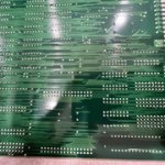
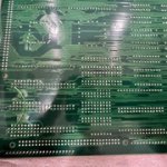
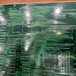
Any chance I could take you up on this? Specifically where each of the red circled jumpers go? Wanting to double-check my work.I have no idea what is going on in this thread, but I have a conversation MW board from like 4 years ago, if anyone needs me to post pictures, just ask.
You are using an out of date browser. It may not display this or other websites correctly.
You should upgrade or use an alternative browser.
You should upgrade or use an alternative browser.
Martial Champion to Mystic Warriors - Conversion/Guide
- Thread starter TheDeath
- Start date
Mystic Warriors Jumpers (from an original board):
JP2 - short
JP3 - short
JP4 - short
JP5 - short
JP6 - long
JP7 - short
JP8 - short
JP9 - short
JP10 - short
JP11 - short
JP12 - short
JP13 - yes
JP14 - yes
JP15 - yes
JP2 - short
JP3 - short
JP4 - short
JP5 - short
JP6 - long
JP7 - short
JP8 - short
JP9 - short
JP10 - short
JP11 - short
JP12 - short
JP13 - yes
JP14 - yes
JP15 - yes
Well I've mirrored these now, and just a black screen. Something's amiss.Mystic Warriors Jumpers (from an original board):
JP2 - short
JP3 - short
JP4 - short
JP5 - short
JP6 - long
JP7 - short
JP8 - short
JP9 - short
JP10 - short
JP11 - short
JP12 - short
JP13 - yes
JP14 - yes
JP15 - yes
Worked still as Martial Champion after installing the second custom. Read/verified all the ROMs as I went, so I'm confident in those.
@XtraSmiley - You wouldn't happen to know what version your ROMs are, would you?
It seems there is JAA, EAA, and UAA. This is what I am finding so far.
It seems there is JAA, EAA, and UAA. This is what I am finding so far.
XtraSmiley
Legendary
I think mine is the JAA one, but can I tell from just booting the game?@XtraSmiley - You wouldn't happen to know what version your ROMs are, would you?
It seems there is JAA, EAA, and UAA. This is what I am finding so far.
I assume you'd see it when it boots up, or maybe somewhere in the test menu. (If its not obvious on the title screen)can I tell from just booting the game?
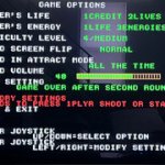
What makes you think its JAA? I was reading the JAA doesnt loop like the other versions (see pic)
https://mycophobia.org/mystwarr.html
Attachments

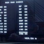
@XtraSmiley - Ahh! It says it on the RAM check!
Attachments

XtraSmiley
Legendary
OK, here you guys go.
https://ibb.co/0sbCNSG
https://ibb.co/VpFFQYy
https://ibb.co/K0nRYVG
https://ibb.co/r6mP2zy
https://ibb.co/DzGxd0t
https://ibb.co/BPL5jS0
https://ibb.co/GtHbLG
https://ibb.co/brfG8JL
https://ibb.co/qCtypd5
https://ibb.co/R730G3Q
https://ibb.co/7z7vw3G
https://ibb.co/NtQYDnV
Looks like it's the EAA version and you can loop it based on the menu settings.
Also, I know I'm late, but I hope this helps @rewrite
Attachments
-
 IMG-4835.jpg20 KB · Views: 104
 -
 IMG-4834.jpg11.9 KB · Views: 88
 -
 IMG-4833.jpg18.7 KB · Views: 89
 -
 IMG-4832.jpg18.5 KB · Views: 92
 -
 IMG-4831.jpg19.6 KB · Views: 93
 -
 IMG-4830.jpg19.1 KB · Views: 98
 -
 IMG-4829.jpg19.1 KB · Views: 95
 -
 IMG-4828.jpg19.2 KB · Views: 94
 -
 IMG-4827.jpg18.9 KB · Views: 91
 -
 IMG-4826.jpg20.7 KB · Views: 97
 -
 IMG-4825.jpg19.4 KB · Views: 108
 -
 IMG-4824.jpg19.5 KB · Views: 105
Last edited:
No worries at all, Sir. Thanks a ton.Also, I know I'm late, but I hope this helps @rewrite
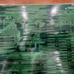
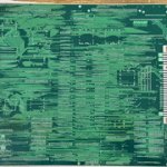
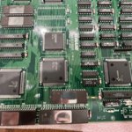
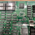
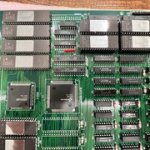
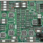
Interesting, looking at your pictures your JP4 and JP11 are in the long position, which doesn't match with my original board.
The instructions for the conversion don't match your original board either. I had to change a few of the circled ones back (not that it did anything).Interesting, looking at your pictures your JP4 and JP11 are in the long position, which doesn't match with my original board.
there's a good chance that some of the jumper positions don't matter. or also possible that certain jumpers are for Mask ROMs vs EPROMs
XtraSmiley
Legendary
Well, when you guys figure it all out, post the results in the first post for future converters.
Would it help at all if I contacted the guy who I bought this from? I'm not sure he would or would not jump in there to contribute.
Would it help at all if I contacted the guy who I bought this from? I'm not sure he would or would not jump in there to contribute.
nah, I'll work it out and post the details. I have a non-working Mystic Warrors on a rusty PCB that looks like it came out of a swamp so I'm planning to PCB swap it to a mint Martial Champions donor. so I plan on going through the boards side by side to understand the differences.
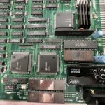
went through the boards side by side and here are the differences I documented:
Remove:
17D - 053990 Custom
Change:
20J - Move from inbound position to outbound position
19J - Move from inbound position to outbound position
17H - Replace with KM62256BLS-10 (SRAM256K100N) and move to outbound position
18H - Replace with KM62256BLS-10 (SRAM256K100N) and move to outbound position
18F - Replace 056472 with 056371 (PAL20L10)
JP2 - From Long to Short Position
JP3 - From Long to Short Position
JP4 - From Long to Short Position*
JP6 - Remove Resistor and replace with 0Ohm Jumper in short position
JF7 - Remove Resistor and replace with 0Ohm Jumper in long position
JP10 - From Long to Short Position
Install:
14B - 24MHz Crystal
CN3 - JST NH 15POS Header
CN4 - JST NH 15POS Header
RA5 - A102J (RA1KX4)
5F - 054539 Custom
ROMs:
20F - 27c020
20G - 27c020
19F - 27c040
19G - 27c040
18F - GAL22V10 https://wiki.pldarchive.co.uk/index.php?title=Mystic_Warriors
6B - 27c010
1H - 27c800
1K - 27c800
3H - 27c040
22K - 27c800
20K - 27c800
19K - 27c800
17K - 27c800
12K - 27c040
10K - 27c040
2D - 27c160
1D - 27c160
----
*Note: I looked a bit more at JP4... interestingly the factory position seems wrong, it's a 20F and 20G are 2M sized ROMs which should have JP4 in the long position. Though given that this is a smaller sized ROM it's entirely possible that either position will work so long as you're using the correct sized EPROM.
looking at pictures of some of these conversions I see some liberties taken like using 27c322s and other oversized ROMs which could change the jumper configs in places.
Last edited:
AlxUnderBase
Enlightened
Jumpers is a big thing on this pcb ... ive tried the conversion first time and first time i supposed was a problem with soldering of the 054539 custom and i sent the board to Hammy to check it with the game running like this :
View: https://www.youtube.com/watch?v=4RVpVtmUHUk&t=0s
After returnal from @Hammy (he fixed) , ive changed program roms and i installed U.UA set (i like the FBI message) and the game was / is 100% playable :
View: https://www.youtube.com/watch?v=2-MLtUPFlI0
After returnal from @Hammy (he fixed) , ive changed program roms and i installed U.UA set (i like the FBI message) and the game was / is 100% playable :
Ace`
Enthusiast
As mentioned above JP4 should be in the long position as it's for the VPP pin. It'll work in the wrong position but not recommended.
Last edited: